Well Control Equipment

  • The primary function of well control equipment is to maintain control of the wellbore, preventing uncontrolled flows of oil, gas, or water, which can lead to accidents, environmental damage, and loss of valuable resources.

Share to

Overview

Well control equipment refers to a set of specialized tools and systems used in the oil and gas industry to manage and control the pressure within a well during drilling, completion, and production operations. The importance of well control equipment cannot be overstated. It helps ensure the safety of personnel and the integrity of the well and the surrounding environment. For example, in the event of a sudden pressure increase or a kick, the proper functioning of BOPs can prevent a potentially catastrophic blowout. Additionally, effective well control equipment allows for smooth and safe drilling and production operations, minimizing disruptions and risks.

Features

  • Safety Features: Include redundant systems and fail-safes to enhance overall safety.
  • High Reliability: It must be able to function accurately and dependably in critical situations to prevent disasters.
  • Quick Response: Able to act rapidly to control well pressure changes. Like a choke manifold that can adjust the fluid flow quickly.
  • Robust Construction: Built to withstand harsh conditions such as high pressure, temperature variations, and corrosive substances.
  • Easy to Operate: With user-friendly interfaces and controls for efficient handling by the crew. BOP control panel that is intuitive and simple to use.
  • Versatility: Capable of adapting to different well types and operating scenarios. It can be adjusted or configured differently depending on the specific well requirements.
  • Accurate Monitoring Capabilities: Incorporate sensors and gauges to provide real-time data on well conditions. Such as pressure gauges that give precise pressure readings.
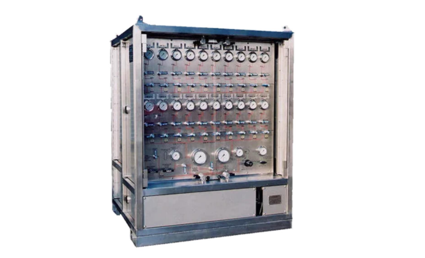
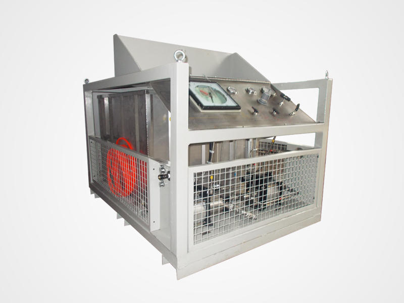
Well Control Equipment
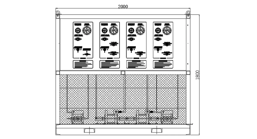
General Layout Drawing of Well Control Equipment

Clear water test

Test mediumClear water
Max. output pressure of low pressure pump60 bar / 6Mpa
Max. output pressure of high pressure pump1500 bar / 150Mpa
Output interfaceG1/4-60°
Pipeline length15 meters (blue)
Pipeline pressure1500 bar / 150Mpa
Number of output interfaces1 with 2

Gas pressure test

Test mediumNitrogen, air
Max. output pressure750 bar / 75Mpa
Output interfaceG1/4-60°
Pipeline length10 meters (color change)
Pipeline pressure750 bar / 75Mpa
Number of output interfaces1 with 1
Nitrogen inlet line length10 meters (black)
Nitrogen inlet threadG1/2

Hydraulic output

Max. output pressure90 bar / 9Mpa
Interface sizeM14*1.5
Hydraulic line pressure250 bar / 25Mpa
Number of hydraulic lines4 each 15 meters (black)

Construction

PanelStainless steel
Water tankStainless steel
Pressure gaugeStainless steel
ValveStainless steel
TubeStainless steel
ConnectorStainless steel
Hydraulic cylinderAnodized aluminium
PistonStainless steel
Pump headStainless steel
FrameCarbon steel

Hydraulic Oil Pressure Static Conditions (@7bar)

Air pressure (bar)01234567
Hydraulic pressure (bar)010203640506070
Output flow rate (L/min)3530243648607284

Water Pressure Static Conditions (@7bar)

Air pressure (bar)01234567
Hydraulic pressure (bar)010025050075001250015001750
Output flow rate (L/min)0.770.650.50.430.380.340.260.2

————————————————————————————————————————————————————————————————————————————————————————————————————————————————————

Related Products