The Most Common 3 Types of Hydraulic Valves & Their Working Principles
You may discover a variety of hydraulic control valves on the market that are made by various manufacturers and are intended to perform a variety of tasks in a variety of applications. While more complex hydraulic systems may employ a combination of valves to perform their job, other hydraulic applications just need a single valve. We’ve highlighted a few of the most popular valves below to demonstrate how they serve different purposes.
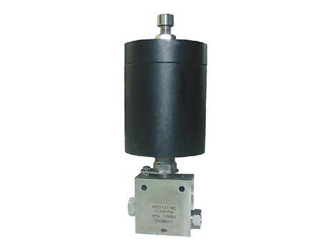
The function of the Hydraulic Control Valve
Spools are included on a number of hydraulic directional control valves. Depending on the position of the spool in the body, spools slide between sections, allowing liquid to flow via open gates. To accomplish the intended port control, valves may have one or many spools. Poppets or plungers are potential additional flow control components in these valves.
The actuator or operator of the valve is the name given to the valve component that powers these flow control devices. These hydraulic valves are capable of providing the correct timing or sequential changes in valve position that are required to regulate hydraulic systems or circuits. For the actuator mechanism, there are a variety of options, including the pilot, electrical/electronic, and mechanical actuation.
Directional Control Valves
What is the directional control valve?
Directional control valves are used to control the flow of fluid through a system, as their name implies. These valves have the ability to regulate the beginning, ending, pausing, and changing of the flow of a pressure medium. They are sometimes known as switching valves for this reason.
The quantity of working ports and spool positions affects how well a directional control valve performs. A directional control valve has two functional ports and at least two spool settings.
The most typical directional control valve has four functioning ports and three spool settings, or a 4/3-way valve. The 2-way directional control valve, which has two ports named inlet and exit, is the most basic directional control valve. The three operating ports of a 3-way directional control valve are known as inlet, outlet, and exhaust. The third working port can stop the flow of all other ports, and they are employed in single-acting cylinders.
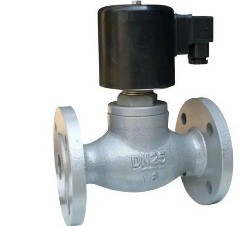
How does the directional control valve work
Discrete hydraulic Directional control valves are a simple form of binary valves, passing and blocking the fluid flow. Using a ball, plunger, or poppet, a check valve shuts the system if fluid attempts to flow in the opposite way.
Multiple gates may be present in hydraulic directional control valves with more complex characteristics since these valves can switch fluid between various ports according to the device they are supplying hydraulic fluid to. As a result, established numbering systems that have two values, such as 4/3 or 2/2, discriminate against them. The first number represents the number of valve ports, while the second one represents the number of valve positions that the apparatus is capable of.
Hydraulic Pressure Control Valves
What is the hydraulic pressure control valve?
The most popular valves used to regulate pressure are valves. They consist of unloading, relieving, reduction, sequence, and counterbalance valves. The hydraulic pressure control valve is essential in preventing pipe or tubing leakage and bursts. By releasing the surplus pressure, pressure control valves control the pressure of the fluid flowing through the pipe or tube. The pressure entered manually by the operator is maintained by these valves.
Almost all hydraulic systems contain pressure-control valves, which help with a number of tasks, including ensuring that system pressures are kept at safe levels and maintaining a specific pressure in a specific circuit.
How does the hydraulic pressure control valve work
The majority of fluid systems are created to function at a specific range of pressures. These valves are essential in stopping pressure increases that could cause hydraulic fluid leaks or the bursting of pipes and tubes. Additionally, they are put in place so that certain areas of a hydraulic circuit have the desired pressure.
Hydraulic systems frequently use reduction valves, relief valves, sequence valves, counterbalance valves, and unloading valves among other pressure control valve types.
Hydraulic Flow Control Valves
What is the flow control valve?
In a hydraulic system, flow control is used to manage speed. Flow control valves modify the flow rate to control an actuator’s speed. The rate of energy transfer inside a system at any given pressure is similarly governed by the flow rate.
The fluid or gas flow through the system is managed and adjusted by flow control valves. Your hydraulic system’s performance can be improved by using these valves. The system’s pressure variations will be monitored, controlled, and prevented from reaching system components through flow control valves.
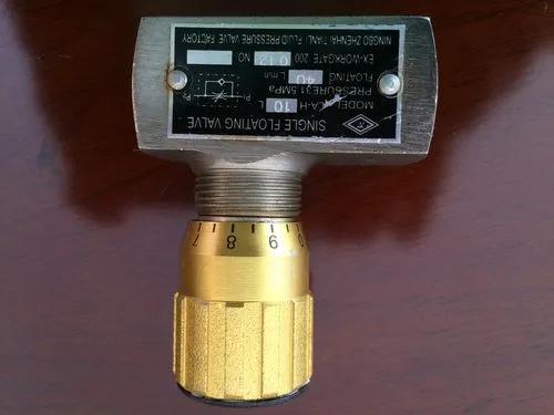
How does the flow control valve work
In hydraulic systems, hydraulic flow control valves are used to manage the flow volume of passing fluid. These valve types have a movable gate that modifies the flow domain to alter the flow rate within the valve. For instance, control circuits for devices like actuators, cylinders, or motors might use this kind of hydraulic valve. These devices’ driving speeds are linearly related to the flow rate, therefore lowering the flow rate lowers it, and vice versa.
Moving flow control valves, pressure-compensated flow control valves, fixed flow control valves, and throttling flow control valves are several varieties of hydraulic flow control valves. The method of flow control in these valves is modified based on the mechanical shape of the valve, which regularly is one of the well-known styles same as other valves, namely:
- Ball
- Butterfly
- Diaphragm
- Needle
- Plug

