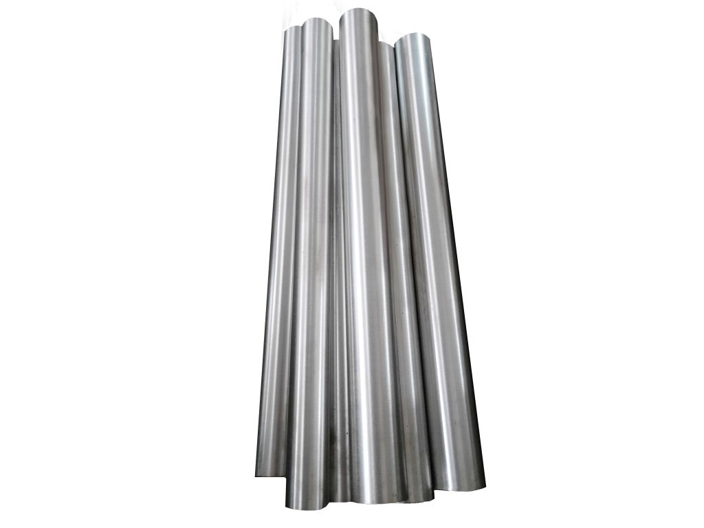
Dissolvable Frac Plug
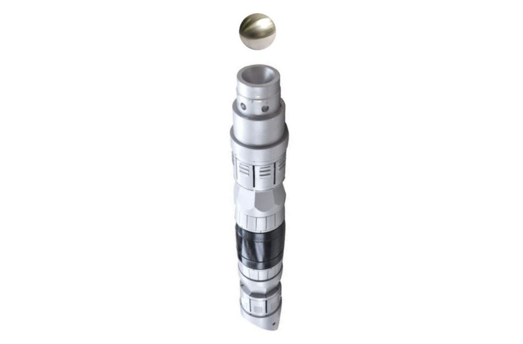
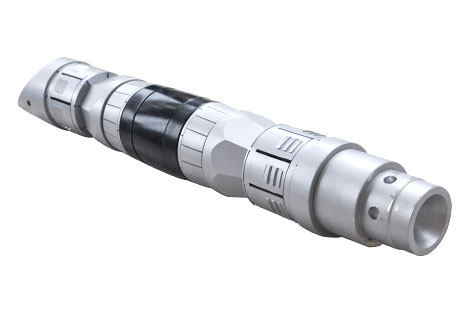
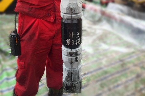
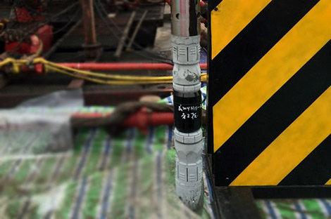
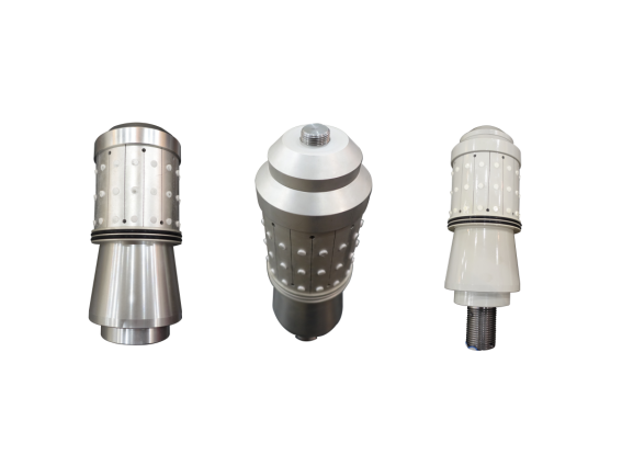
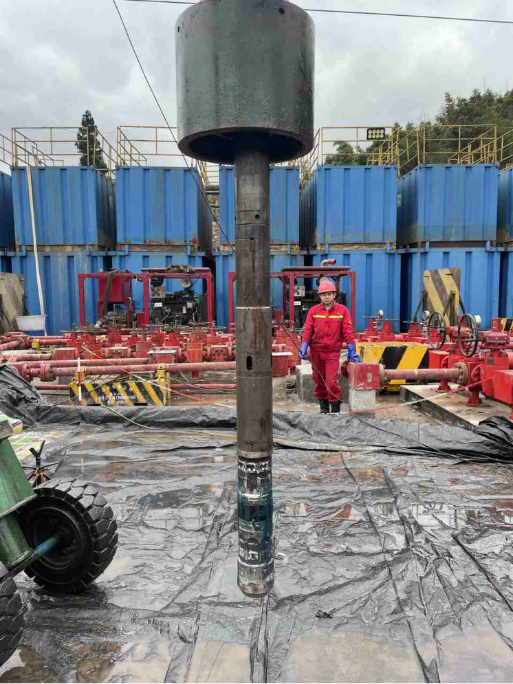
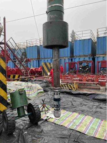
- Dissolvable frac plugs are specialized devices used in the fracturing process to isolate sections of a wellbore during stimulation treatments. Unlike traditional frac plugs, which must be retrieved after use, these innovative devices are made from materials that dissolve in the formation fluid over time.
- They can be engineered to dissolve at specific rates depending on operator needs and well conditions. This precision allows for optimized fracturing treatment cycles, ensuring that formations are accessed effectively without leaving behind contaminants that could hinder future drilling efforts.
Share to
Overview
WINGOIL has developed several series dissolvable bridge plugs upon working temperature (30-150°C), the outer diameter of bridge plug is from 50mm to 110mm. All models are testified in oil and gas well operation with 100% success rate.
Characteristic
- Special cracking technology.
- Customized formula and the solubility time is flexible.
- Special high strength compound slips(max. Strength 1250Mpa), it is stable to long 15 days.
- Made of compound high strength soluble metals, guarantee the material strength under high temperature.
- Good compatibility and inheritance, unnecessary to change existing strings structure, no risks resulted from drilling out and reduce the damage of casings.
Operation Principle
- During operation, the upper end of the releasing ring is connected with the mandrel of the feeding tool through a connecting auxiliary joint, the outer cylinder of the feeding tool is pushed against the thrust ring, and the double-slip elastomer frac plug is delivered to the target setting position by cable or CT.
- After the CCL is calibrated to determine the position, ignite the feeding tool or pumps the liquid into the ground, and the mandrel of the feeding tool is driven by the gas pressure generated by the gunpowder column or the hydraulic pressure generated by pumping in the liquid. Then the relative motion between the mandrel and the outer cylinder is produced, which enables the mandrel of the feeding tool to drive the releasing ring upwards.
- The outer cylinder of the feeding tool is used to compress the thrust ring, which moves downwards. And the thrust ring pushes the upper and lower slip cone, causing the slip to extend outward along the inclined surface. The slip holds the inner wall of the casing for anchoring, and the elastomer cylinder is deformed by pushing pressure to expand the inner cavity of the sealed casing.
- When the thrust force reaches 120-130KN or more, the double-slip elastomer frac plug has been completely set and anchored. Under the pull of the feeding tool’s mandrel, the releasing ring is sheared off, and the feeding tool is separated from the double-slip elastomer frac plug to complete the releasing process.
- After the double-slip elastomer frac plug is set, the channel in the inner cavity of the releasing joint is closed by a single flow, and the fluid can only flow upward from the lower part, and the fluid in the upper part is cut off. When fracturing, the double-slip elastomer frac plug seals the channel of the lower layer, and performs fracturing construction on the upper layer.
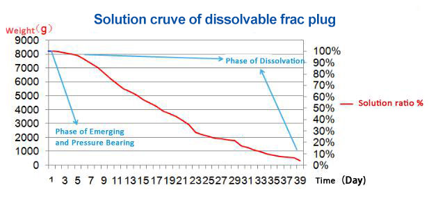
- After fracturing, the fluid in the lower layer can flow through a single flow channel for normal flow or production. During the process of flow and production, the high concentration chloride ion liquid produced by the formation dissolves the double-slip elastomer frac plug in the wellbore fluid and disappear naturally.
Remark
All above specification is based on working temperature 90℃, if the size and dissolution time needs to be customized according to well condition and temperature.
| Model | HHCY457R-110-70-M2 | HHCY457R-106-70-M2 | HHCY457R-103-70-M2 | HHCY457R-98-70-M2 | HHCY457R-98-70-M2 | HHCY457R-88-60-M2 | HHCY457R-83-50-M2 | HHCY457R-50-30-M2 |
| OD (mm) | 110 | 106 | 103 | 98 | 98 | 88 | 83 | 50 |
| ID (mm) | 45 | 45 | 35 | 35 | 35 | 30 | 30 | 20 |
| Casing ID (mm) | 118.6-124.3 | 114.3-124.3 | 114.3-118.6 | 108-114.3 | 108-114.3 | 97-114.3 | 95-114.3 | 58-64 |
| Casing OD (in.) | 5.5 | 5.5 | 5.5 | 5 | 5 | 4.5-5 | 4.5-5 | 2⅞ |
| Casing Weight (lb/ft) | 17-23 | 17-26.8 | 23-26.8 | 13-15 | 13-15 | 12.6-15 | 12.6-15 | 6.4-6.5 |
| Plug Length (mm) | 425 | 425 | 370 | 424 | 299 | 398 | 428 | 330 |
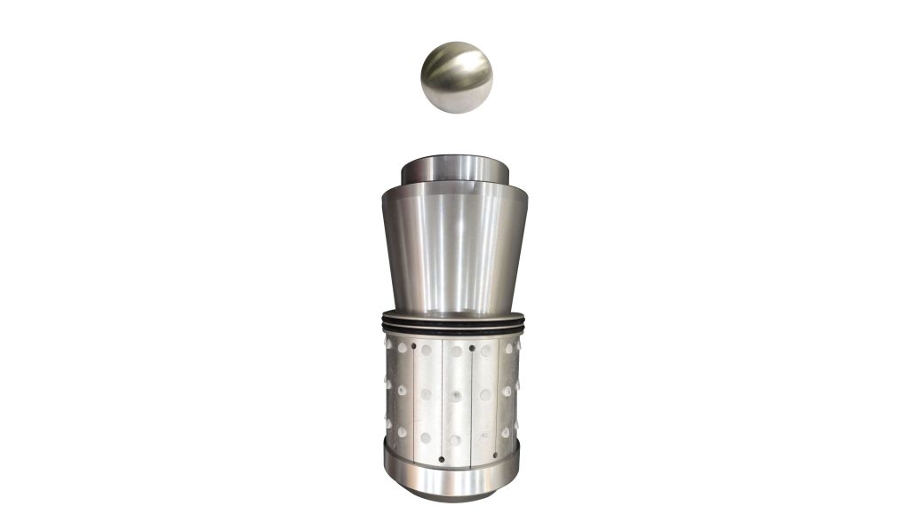
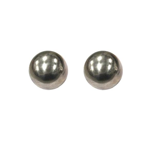
| Dissolvable Ball (mm) | 54 | 54 | 47.625 | 47.625 | 54 | 47.625/54 | 47.625/54 | 28 |
| Pressure Differential (MPa) | 70 | 70 | 70 | 70 | 70 | 60 | 50 | 30 |
| Work Temp. | 30-150°C | 30-150°C | 30-150°C | 30-150°C | 30-150°C | 30-150°C | 30-150°C | 30-150°C |
| Setting Tool | Baker #20 | Baker #20 | Baker #20 | Baker #20 | Baker #20 | Baker #10 | Baker #10 | Baker #5 |
| Release Method | Upper | Upper | Lower | Upper | Lower | Lower | Lower | Upper |
| Force (T) | 14-16 | 14-16 | 14-16 | 14-16 | 14-16 | 10-12 | 10-12 | 3-4 |
| Working temperature | 50 to 150℃ |
| Sealing pressure | 700 bar / 70 Mpa |
| Dissolution medium | 1% KCl solution |
| Sealing Effective Time | 8/24/40 hours |
| Dissolution time | 8/15/30 days |
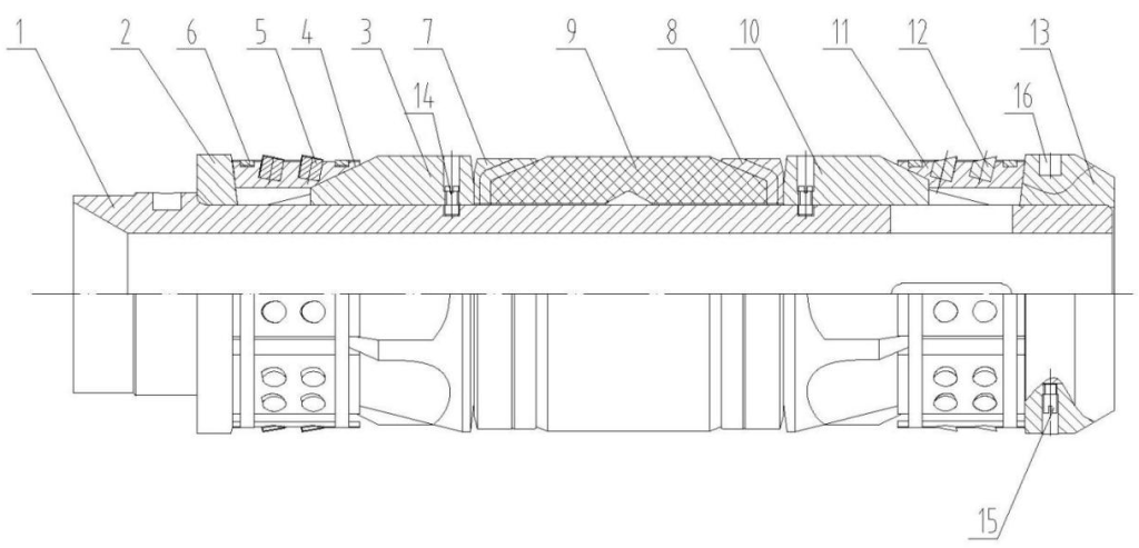
1-Mandrel 2-Thrust Ring 3-Upper Cone 4-Upper Expansion Slip 5-Bite Button 6-Slip Ring
7-Lower Protective Cover 8-Central Protective Cover 9-Elastomer Cylinder 10-Lower Cone 11-Lower Expansion Slip
12-Bite Button 13-Anti-collision Ring 14-Shear Pin 15-Shear Pin 16-Anti-grinding Button
————————————————————————————————————————————————————————————————————————————————————————————————————————————————————

