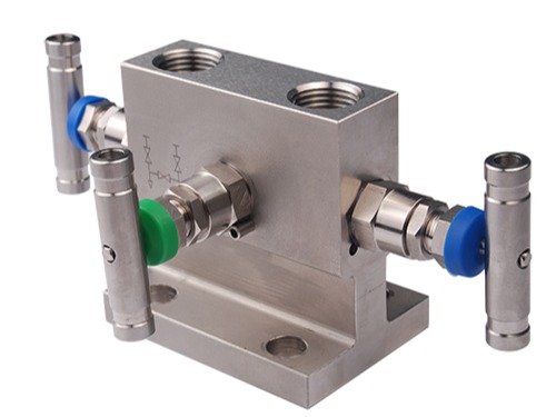
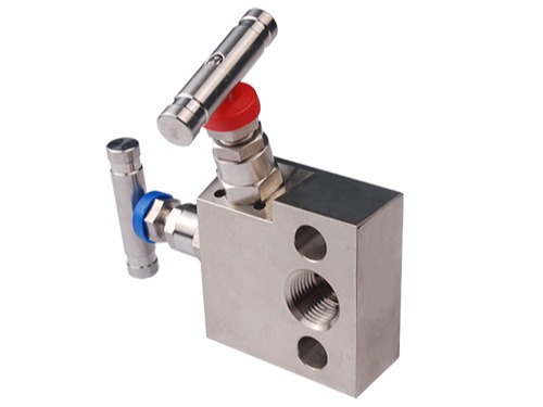
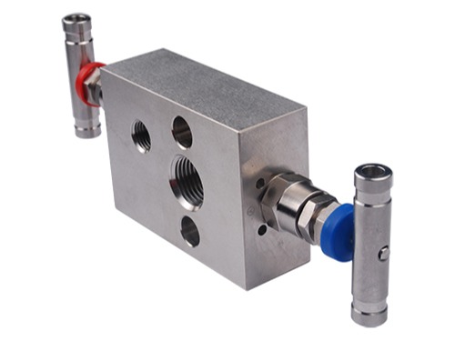
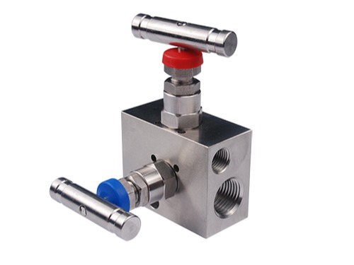
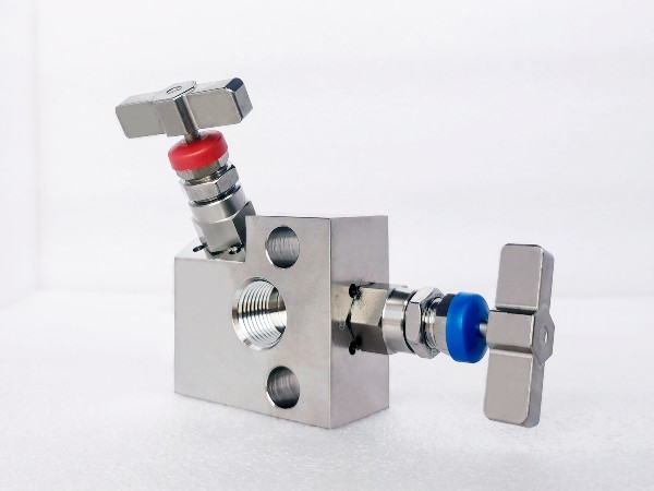
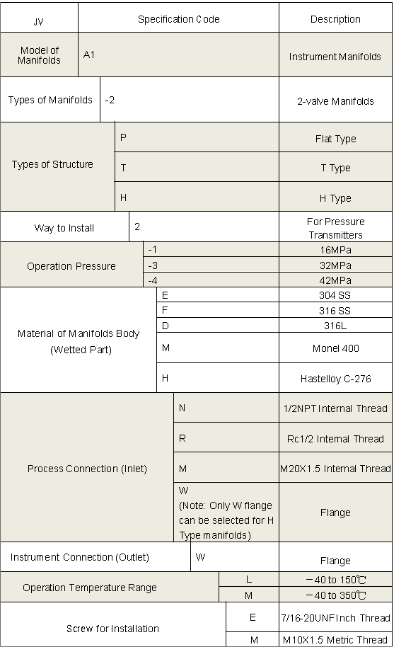
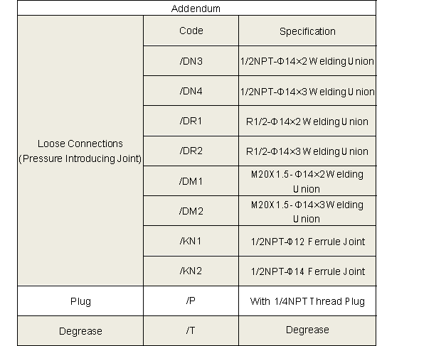
2-Valve Manifolds
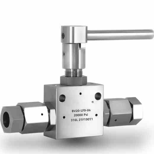
- The valve tip adopts cone surface and rear ball head design, providing smaller opening and closing torque and longer service life.
- The sealing part of the valve stem is processed by extrusion, with a surface roughness of Ra0.1, which reduces friction with the packing and improves the service life of the valve stem and packing.
- The valve body sealing port adopts an automatic centering design to ensure that the valve tip sealing line is in the same position each time it is shut off.
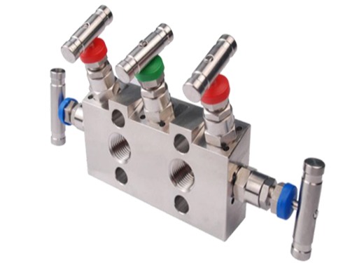
- Blue, green and red are used to distinguish shut-off valves, balance valves and drain/test valves, making the installation site clear at a glance.
Share to
Overview
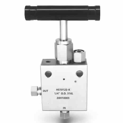
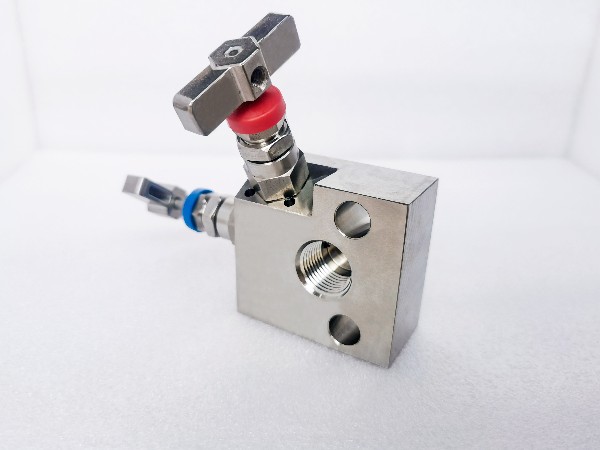
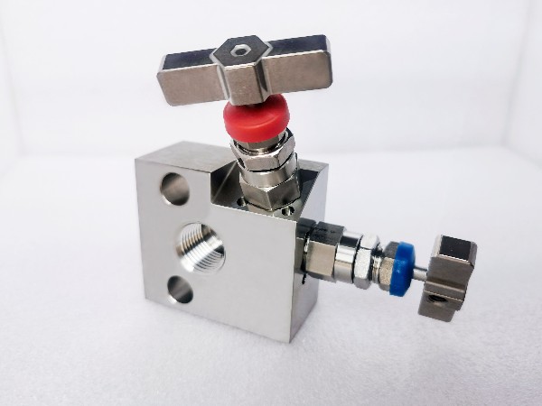
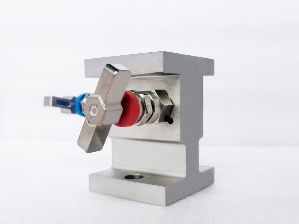
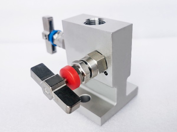
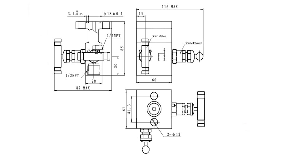
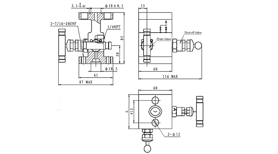
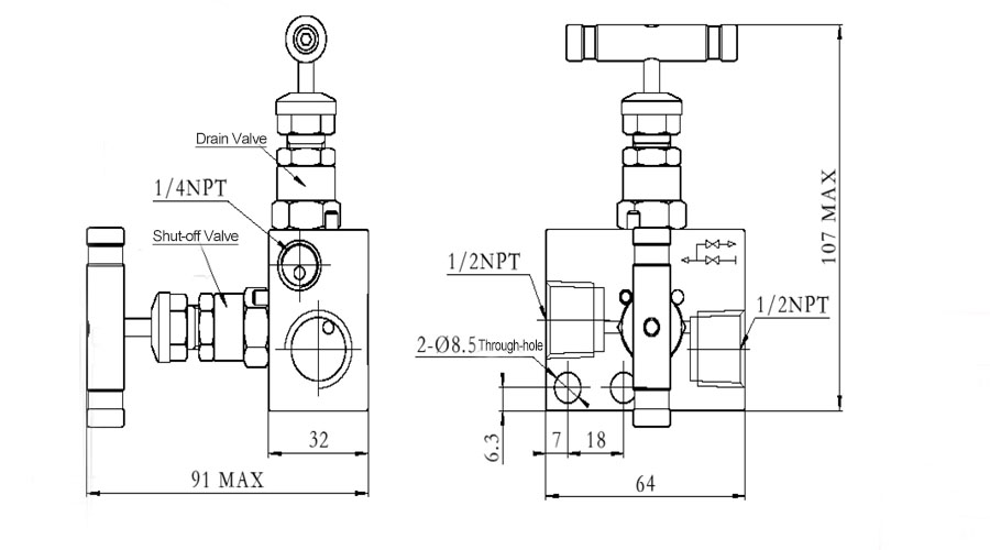
The valve manifolds and valves have nice appearance, compact structure and reliable sealing feature. They can be installed in conjunction with various differential pressure/pressure transmitters and pressure instruments to open, cut off and discharge the flow rate, pressure, pressure difference and liquid level. They are also convenient for on-site installation, commissioning, maintenance and inspection of instruments. The main structural types are: Flat type, T type, H type and column type.
Features
- Integrated structure, safe and reliable.
- Stainless steel pins are used to prevent the valve seat from coming off due to vibration.
- Burr-free threads and internal surfaces reduce leakage and ensure accurate meter readings.
- The valve seat and the valve body are hard-connected to provide a reliable zero-leakage seal.
Operating Principle
The 2-Valve Manifold consists of a valve body, one shut-off valve, and one drain valve, with a drain outlet of 1/4NPT thread.
- Operating procedure: Close the shut-off valve and drain valve first, and slowly open the shut-off valve during operation until it’s fully open. Finally, the transmitter is put into normal operation.
- Calibration procedure: Close the shut-off valve and drain valve, connect the pressure connector from the 1/4NPT drain outlet, and slowly open the drain valve until it’s fully open.
- Maintenance procedure: Close the shut-off valve, open the drain valve, and discharge the medium inside the manifold from the 1/4NPT drain outlet. Be careful not to face people directly. At this time, the manifold can be repaired and maintained.
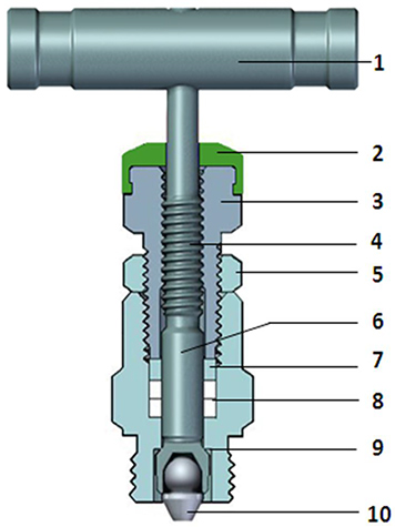
- 1. The handle is equipped with an anti-loosening screw to better transmit torque.
- 2. Blue, green and red dust covers are used to distinguish shut-off valves, balance valves and drain/test valves, and to prevent dust and impurities from entering the valve stem and affecting the sealing process.
- 3. The gland nut is used to push the packing to deform and expand it, forming a seal with the valve stem and valve seat. If there is a slight leakage, it can also be adjusted twice or multiple times.
- 4. The valve stem adopts rolling thread to improve the surface hardness of the thread, making it more wear-resistant and extending the service life of the valve stem.
- 5. The locking nut provides reliable locking force to prevent the gland nut from loosening due to vibration, causing the packing to lose its sealing function.
- 6. The sealing part of the valve stem is processed by extrusion, with a surface roughness of Ra0.1, which reduces friction with the packing and improves the service life of the valve stem and packing.
- 7. Metal washer provides non-rotating thrust and reduce packing damage due to rotational friction.
- 8. Bottom design PTFE/flexible graphite packing prevents media from entering and corroding the valve stem threads.
- 9. When the valve is fully opened, the conical surface on the back of the valve stem forms a linear contact with the valve seat, providing auxiliary sealing for the valve stem.
- 10. The dual-phase steel cone head provides higher hardness to avoid damage after repeated use. The tail ball head design provides non-rotating push, and the head taper design forms a linear sealing with the valve body orifice. The overall universal swing design reduces the sealing risks caused by different shafts of other parts.
————————————————————————————————————————————————————————————————————————————————————————————————————————————————————